What Is a VTOL Airframe and How Does It Work?
A Vtol Airframe combines vertical lift with forward flight in one carefully balanced structure. It can rise from a small landing area, hover above uneven ground, and transition toward efficient cruising. This flexibility makes VTOL aircraft useful for emergency response, surveying, inspection, logistics, and other demanding operations.
The airframe carries motors, batteries, flight controls, landing equipment, and payloads. Its shape must manage weight, vibration, airflow, heat, and structural stress. During takeoff, rotors or lift fans generate upward thrust. During cruise, wings may provide most of the lift. Some designs tilt their rotors, while others use separate systems for hovering and forward movement.
The trade-offs matter. A heavier battery can extend endurance, yet it also increases lift requirements. A larger wing may improve cruise efficiency, but it can complicate compact landing operations. Engineers therefore test materials, propulsion layouts, control software, and transition behavior under controlled conditions. Every gram counts.
This guide explains how a Vtol Airframe works, how its major components interact, and why configuration choices affect performance. It also examines stability, energy use, maintenance, and operational safety through established aerospace principles. Real-world results can differ from laboratory predictions. Wind gusts, temperature, payload changes, and imperfect calibration may expose weaknesses that diagrams overlook. That is why reliable design depends on simulation, physical testing, documented procedures, and continuous review. Understanding these limits gives readers a clearer, more practical view of VTOL technology, rather than presenting it as a simple solution for every flight mission.
Definition and Core Features of a VTOL Airframe
What Is a VTOL Airframe and How Does It Work?
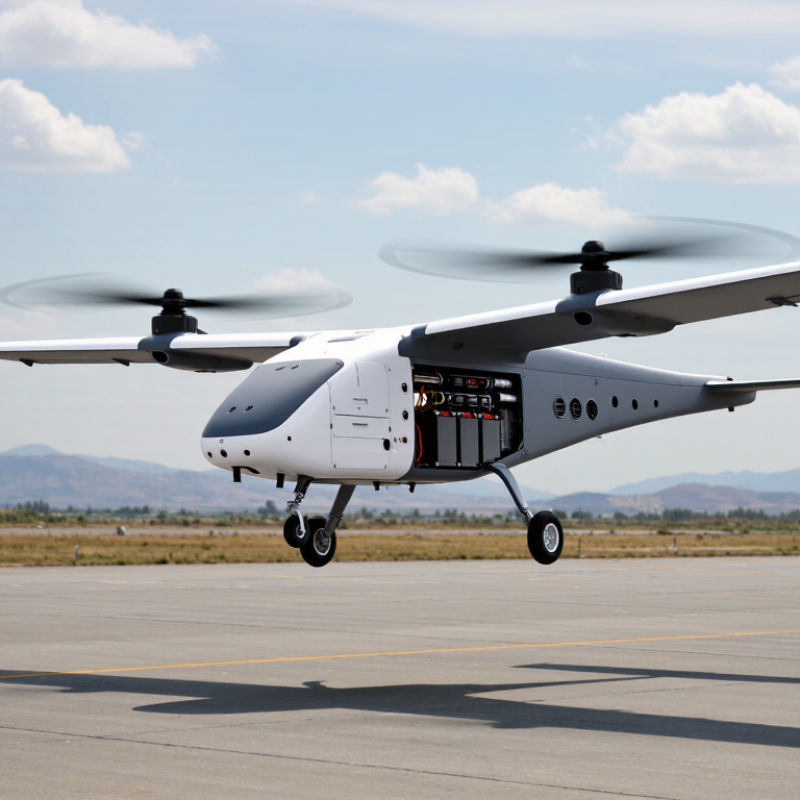
A VTOL airframe can take off and land vertically without a runway. Its structure must manage lift, weight, vibration, and changing airflow. During takeoff, rotors, propellers, or lift fans push air downward. In forward flight, wings may carry most of the load. The transition is the difficult part.
The airframe usually combines a lightweight fuselage, reinforced attachment points, energy storage, flight-control computers, and distributed lifting units. Engineers inspect these areas closely because small cracks near motor mounts can spread under repeated vibration. The Vertical Flight Society’s 2024 World eVTOL Aircraft Directory listed more than 900 reported concepts and projects. That figure shows strong interest, but it does not prove technical readiness. Numbers can mislead.
Core VTOL features include low-speed stability, controlled transition, redundancy, and precise landing authority. Redundant systems matter. One failed lifting unit should not immediately remove safe control. The FAA’s 2024 powered-lift rule created a dedicated regulatory framework for this aircraft category, reflecting its different operating demands. Yet certification remains complex. Battery mass, thermal management, noise, and emergency descent performance can reshape the entire airframe. NASA’s advanced air mobility research also treats community noise and operational safety as key evaluation factors. A quiet aircraft is not automatically a safe one. The airframe must still perform reliably in wind, rain, heat, and imperfect maintenance conditions.
What Is a VTOL Airframe and How Does It Work?
A VTOL airframe is designed to take off and land vertically while supporting controlled flight in the air. The chart compares common VTOL configurations by their core flight capabilities.
Multicopters rely on rotors for lift and propulsion, lift-plus-cruise designs use separate vertical-lift and forward-flight systems, tiltrotors redirect their rotors during transition, and tailsitters rotate the entire airframe between vertical and horizontal flight.
Main Components and Structural Design
A VTOL airframe supports vertical takeoff, hovering, and forward flight through carefully arranged lifting structures. Its frame must resist vibration, bending, landing shocks, and changing aerodynamic loads. Engineers usually begin with clear load paths. Thrust, rotor forces, and payload weight must travel through reinforced joints into the main fuselage. Weak connections can create fatigue cracks over time.
The main components include the central fuselage, lifting arms, motor mounts, landing gear, control surfaces, and removable access panels. Lightweight composite skins may cover a stiff internal frame, while aluminum or other approved alloys can strengthen high-load attachment points. Each motor mount needs accurate alignment. Even a small angle error can increase vibration and reduce efficiency. Landing gear also needs controlled flexibility. Rigid gear may transfer harsh impact forces into the cabin structure.
Weight distribution strongly affects stability. Batteries, fuel systems, sensors, and cargo should remain close to the designed center of gravity. Designers often use bulkheads, longerons, and cross-braces to prevent twisting. In practical inspections, technicians check fasteners, bonding areas, and surface damage around joints. These details are easy to overlook.
This balance is rarely perfect. A lighter frame may require more frequent inspection. A stronger frame can reduce useful payload. Structural simulations help, but real vibration data can reveal unexpected weaknesses. Good design leaves room for repair, drainage, wiring access, and future modifications. Otherwise, a technically sound airframe may become difficult to maintain.
Flight Transition from Hovering to Forward Motion
What Is a VTOL Airframe and How Does It Work?
Flight Transition from Hovering to Forward Motion
A VTOL airframe can rise vertically, pause in the air, and then travel forward like an airplane. Its transition system coordinates rotors, propellers, wings, and control surfaces. During hovering, vertical thrust carries the aircraft’s weight. The wings produce little useful lift because airflow remains limited. Precise control is essential here. Small changes in thrust can cause noticeable movement.
The transition begins when the aircraft tilts its thrust direction or changes rotor position. Forward acceleration increases airflow across the wings. As airspeed builds, the wings gradually create more lift and reduce the burden on the vertical propulsion system. A flight controller continuously adjusts pitch, thrust, and roll. Sensors provide data on speed, attitude, altitude, and motor performance. The process must remain stable through the middle stage. This is the most demanding part.
No transition is perfectly smooth. A slight control delay can create a nose drop or unwanted yaw. Engineers use test flights, simulation, and conservative speed limits to reduce these risks. They also examine vibration, battery temperature, structural stress, and emergency recovery behavior. A useful design is not merely fast. It must respond predictably when wind changes or a sensor becomes unreliable. Some aircraft still consume considerable energy during transition. That limitation deserves more attention. Better efficiency may require slower acceleration, larger wings, or a more complex control strategy.
Major VTOL Airframe Types and Practical Applications
What Is a VTOL Airframe and How Does It Work?
Major VTOL Airframe Types and Practical Applications
A VTOL airframe can rise, hover, and land without a runway. Its propulsion system produces vertical lift during takeoff. Afterward, the aircraft may shift toward efficient forward flight. This transition requires careful control of thrust, balance, and airflow. Small errors can create noticeable vibration.
Multicopter airframes use several vertical rotors. They are mechanically simple and responsive, making them useful for aerial inspection, site mapping, photography, and emergency observation. Their weakness is endurance. Batteries drain quickly during sustained hovering.
A lift-plus-cruise design separates vertical rotors from forward propellers. It usually flies farther, but carries extra motors and structural weight.
Tilt-rotor airframes rotate their propellers or engines from vertical to horizontal positions. They combine runway-free operation with faster cruise performance. However, the transition phase demands precise software and reliable sensors.
Tailsitter aircraft take off on their tail, then pitch forward for cruise. They save weight but can be awkward during landing. In practical field trials, wind, dust, and uneven ground often expose weaknesses that computer models miss.
The best airframe depends on mission distance, payload, noise limits, maintenance skills, and available landing space. No design wins every time.